
Precision Motion through Mechanical Logic
Exploring synchronized motion through calculated tolerance and 3D-printable geometry
No fasteners. No motor. Motion comes entirely from printed gear geometry.
A fully integrated 15-gear assembly driven by lead-screw logic, demonstrating that complex synchronization can be achieved through calculated tolerances rather than added fasteners or motors.
Status: Final Functional Prototype: 15-Gear Synchronization
From Principle to Product
Five development phases across 11 iterations
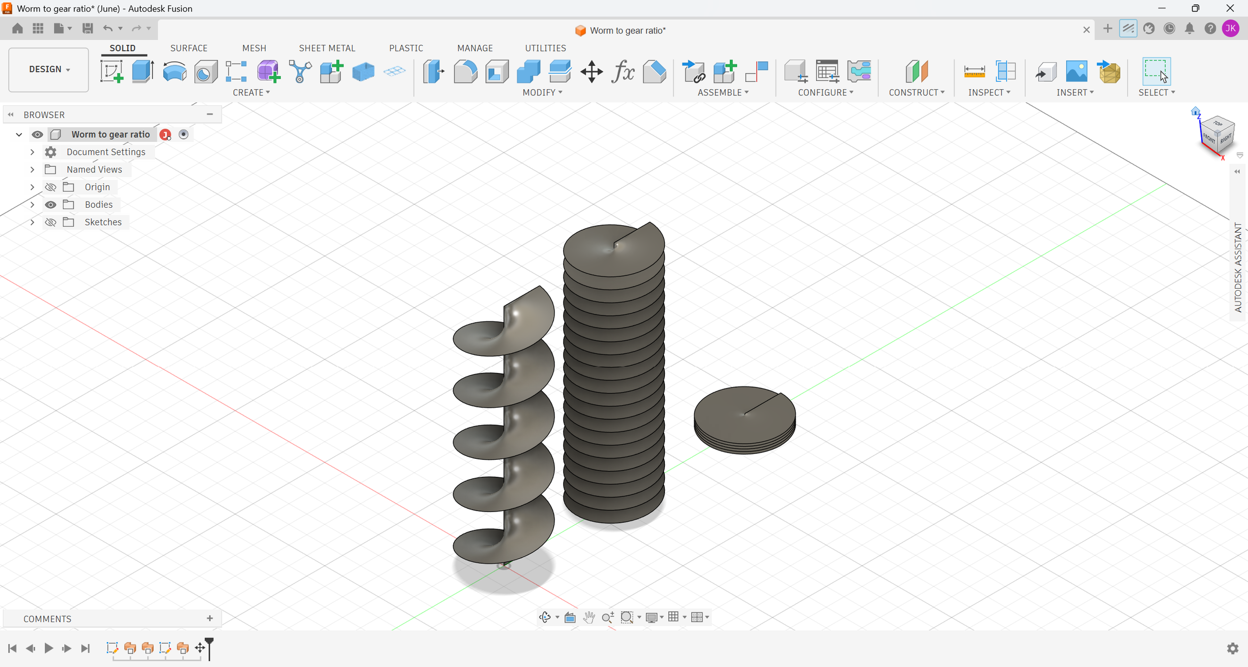
Phase 0 — Principle verification. The worm-and-gear ratio was tested in isolation before the full assembly was designed.
Phase 2 — Tolerance refinement. Guide posts and split shafts introduced to control alignment.
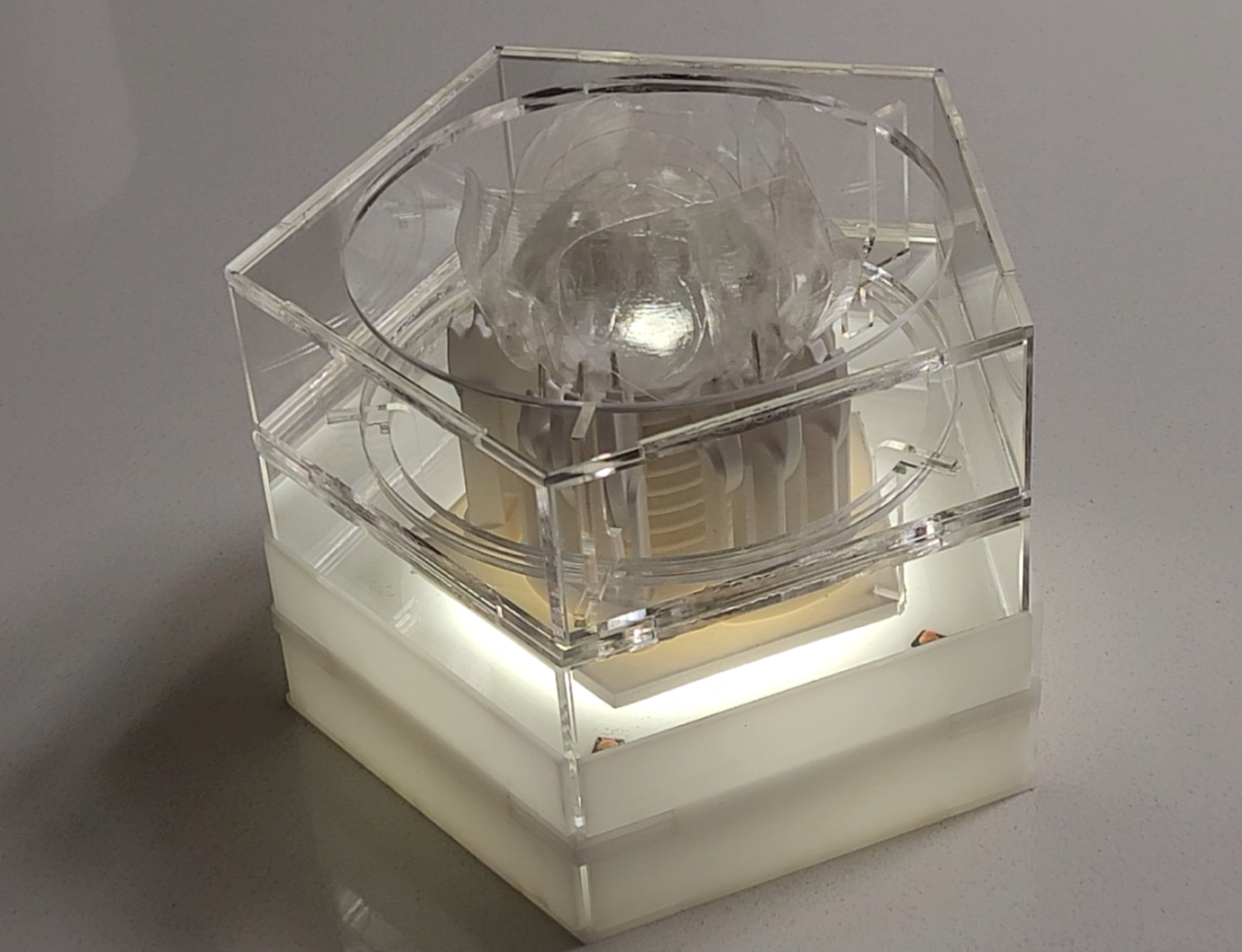
Phase 4 — Final form. The 15-gear assembly was housed in transparent acrylic.
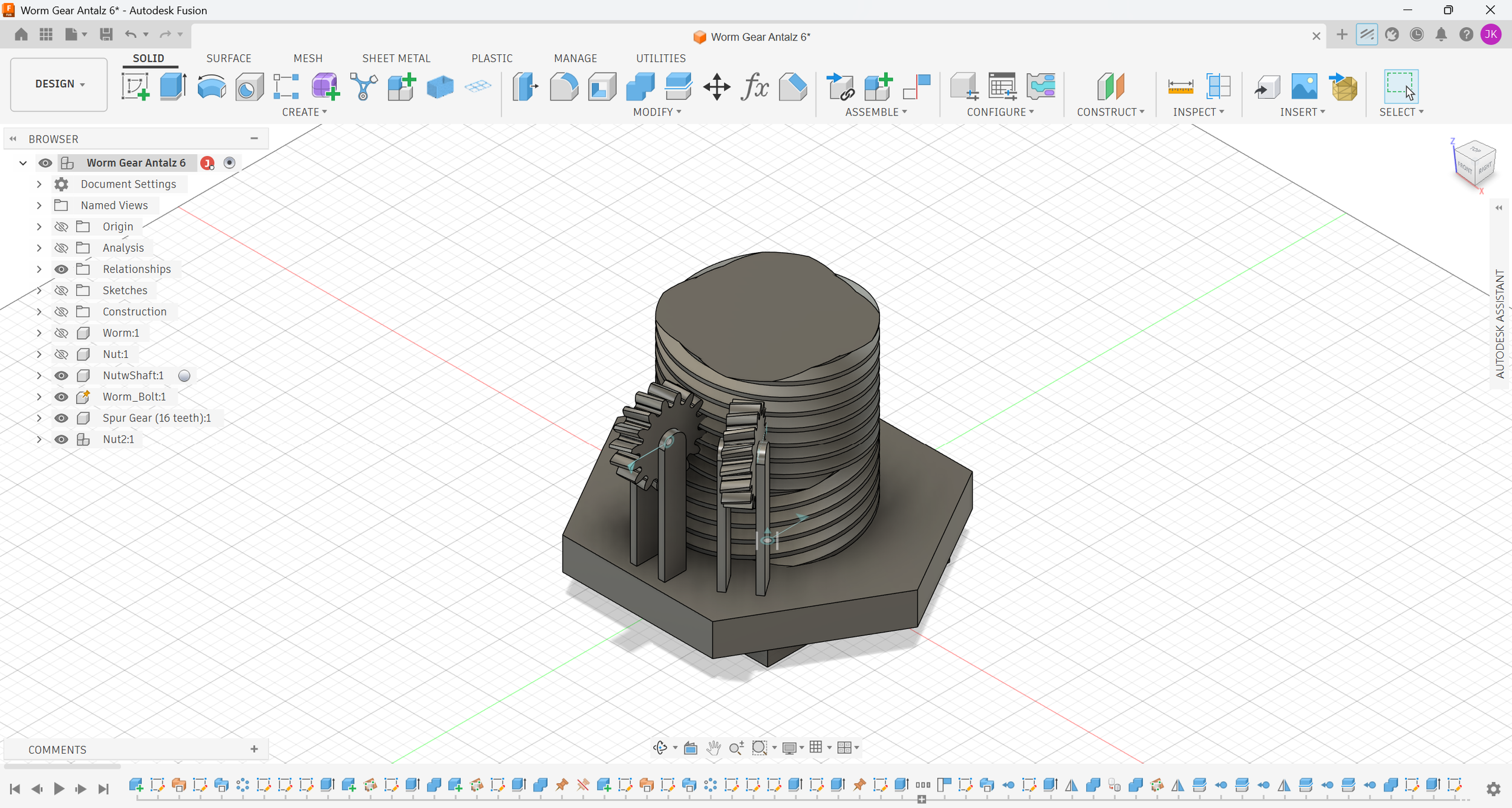
Phase 1 — Assembly architecture. Gear train arranged on a base; joints defined in CAD.
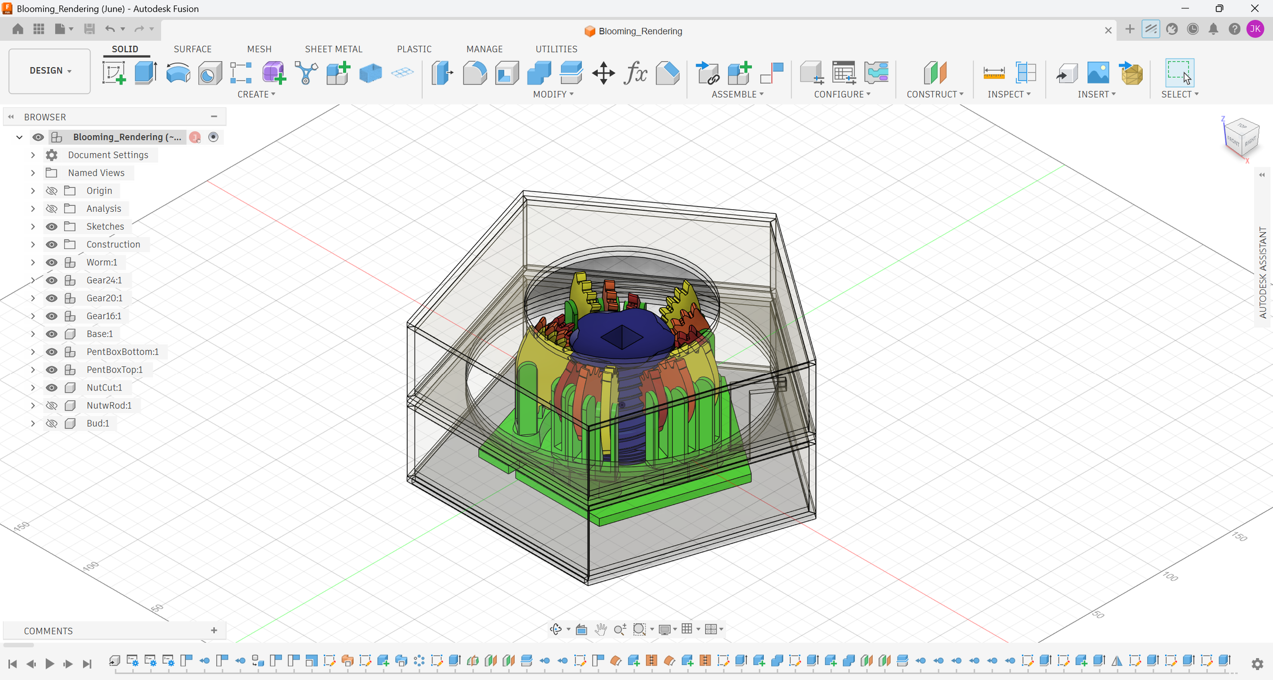
Phase 3 — Full-body integration. Mechanism and form merged into a single printable architecture.
CAD shows you the geometry. Only the print shows you the fit.
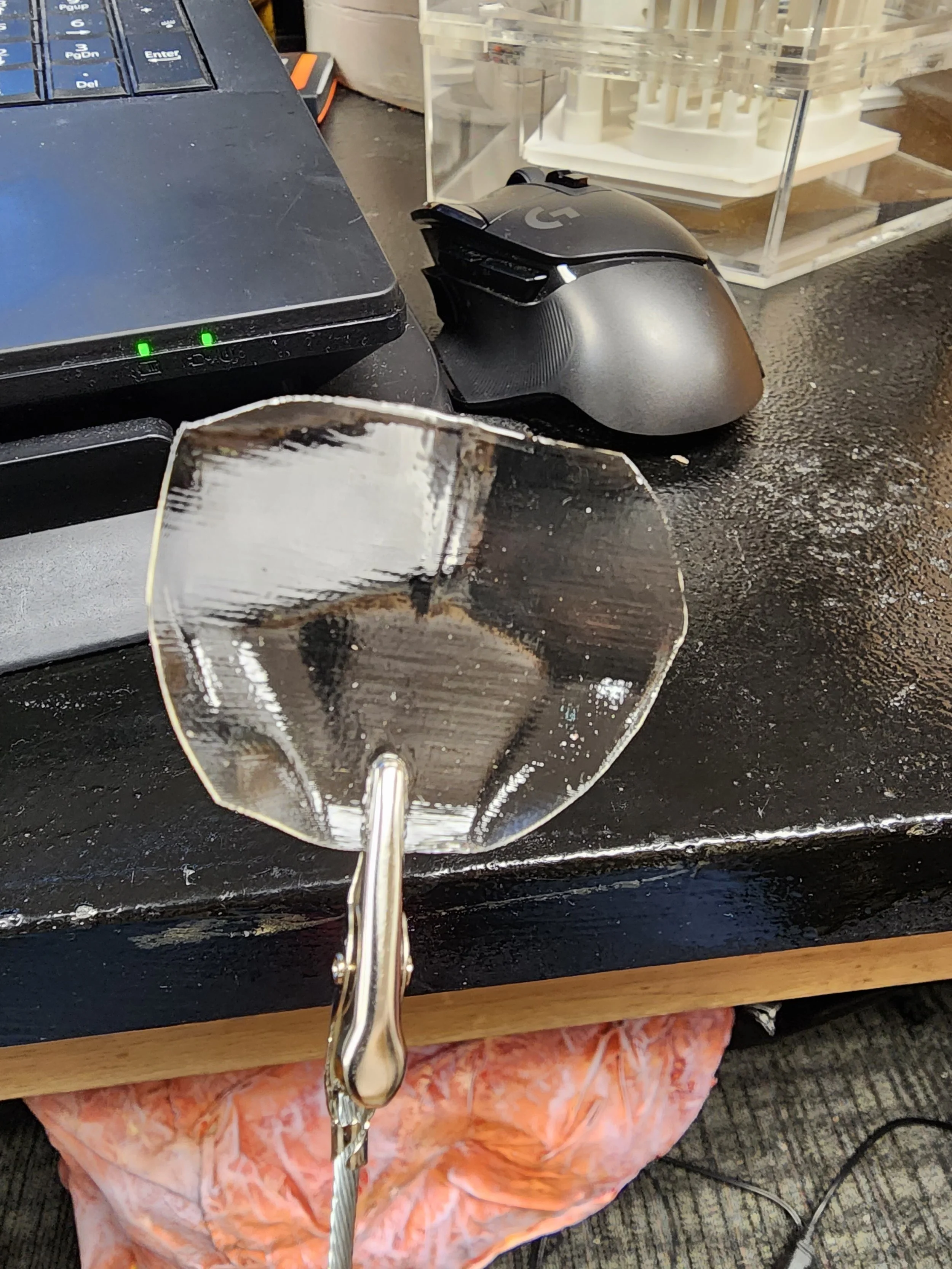
After Vapor Smoothing
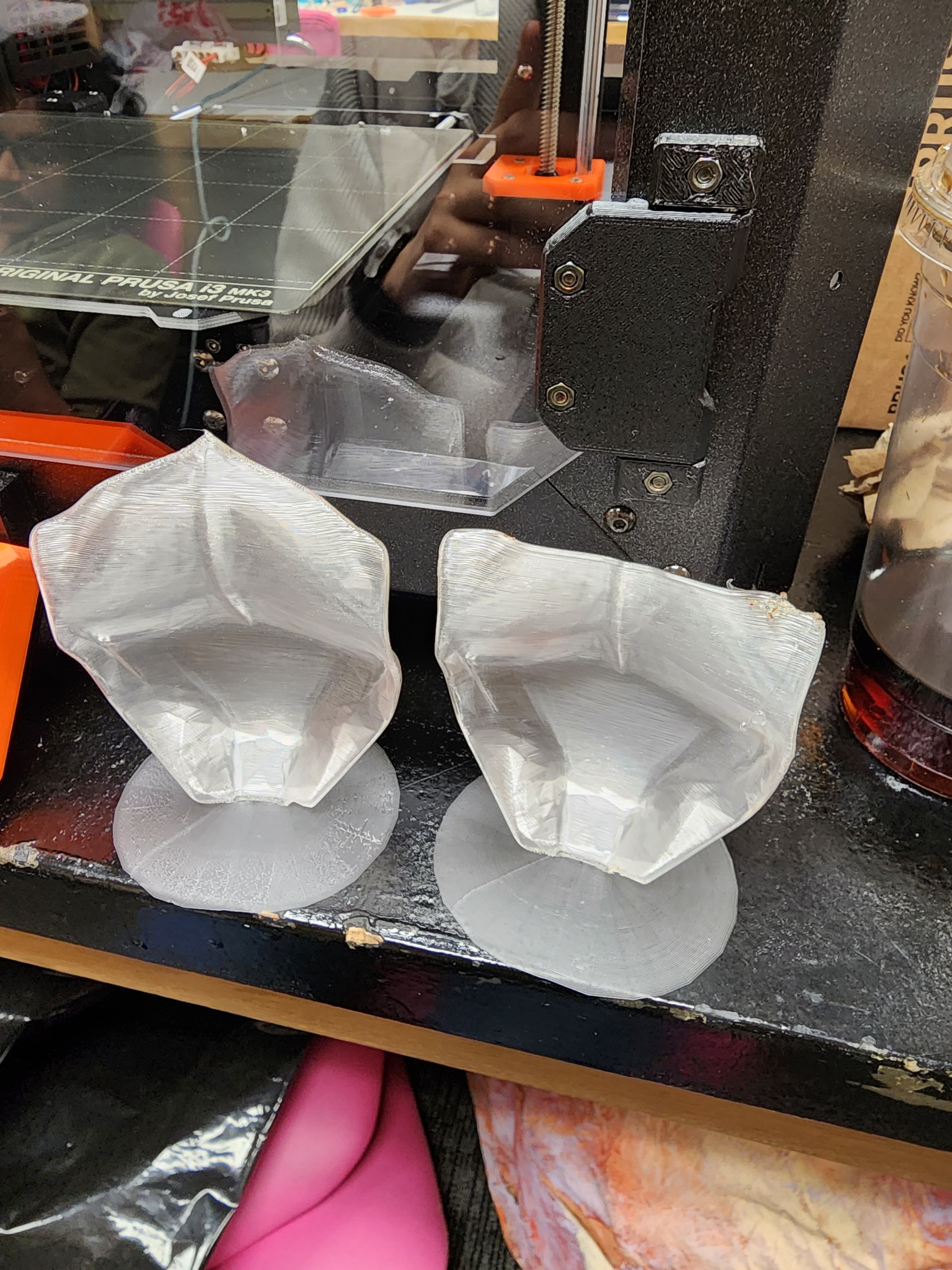
Before Vapor Smoothing